
http://wiki.x-plane.com/Chapter_6:_Advanced_Features_of_X-Plane_for_iPad/X-Plane_HDEF_4G
X-Plane for iPad manual
第6章: iPad/X-Plane HDEF 4Gの先進機能
Note: This chapter assumes prior familiarity with the workings of the view options and the Settings menu, as well as with the standard flight instruments. All of this is described in Chapter 2: Getting Acquainted with the iPad/iPhone 4G Simulator.
注意:この章では、以前のビューオプションの仕組みに精通し、[設定]メニューだけでなく、標準的な飛行計器とを前提としています。アプリ/ iPhoneの4Gシミュレータ各部の名称と働き:これのすべては、第2章で説明されている。
Contents
Flying an Approach Using the Instrument Panel
インストゥルメントパネルを使用したフライングアプローチ
Nearly all of the aircraft in X-Plane for iPad/X-Plane HDEF 4G have basic navigation radios and instruments built into them, and all of these are used in more or less the same way. We will go through an example for flying an ILS approach (that is, an approach using an instrument landing system) in the Southern California region, but similar steps can be used for any airport.
Note that instrument navigation is not for the faint of heart. X-Plane is as realistic a flight simulator as possible, and navigation is no exception. This section is by no means a complete guide to airplane navigation (there are plenty of 400-page books available that claim that), but it will go into quite a bit of detail. We will discuss a great deal of side information needed to fly all approaches, but we will always come back and relate it to flying the example approach into San Bernardino International (again, found in the Southern California region).
To fly an instrument approach, users will first need to know the local navigational aid (NAVAID) frequencies. To find this, tap the center of the screen to make the various menu options appear, then open the Settings menu.
The map in the window that appears shows the ILS, LOC, VOR, and VORTAC frequencies for the area. Zoom in and out of the map by placing two fingers on the screen and dragging them farther apart (to zoom in) or closer together (to zoom out). To pan the map, place one finger on the map and drag it, and to rotate it, place two fingers onto the map and twist them in a circular motion.
Let's discuss the specifics of each of these types of navigational aids (NAVAIDs)
ほぼすべてのiPad/X-Plane HDEF 4GのためのX-Planeにおける航空機の基本的なナビゲーションは、ラジオ、それらに組み込まれた器具を有し、これらの全ては多かれ少なかれ同じように使用されている。私たちは、南カリフォルニア地域で(つまり、計器着陸装置を使用したアプローチである)のILSアプローチを飛行するための例示を通過しますが、同様の手順では、空港を使用することができます。
その機器のナビゲーションは心臓の弱い人のためではないことに注意してください。 Xプレーンは、可能な限り現実的なフライトシミュレータであり、ナビゲーションも例外ではない。このセクションでは、それは細部にかなりに入ります(そのクレーム利用可能な400ページの本がたくさんあります)決して飛行機ナビゲーションへの完全なガイドです。我々は、すべてのアプローチを飛行するのに必要なサイド情報を大量に説明しますが、我々は常に戻ってきて(再び、南カリフォルニア地域にある)サンバーナーディーノ国際への例のアプローチを飛行に関連します。
計器進入を飛行するには、ユーザーは最初にローカル航行援助( NAVAID )周波数を知っている必要があります。これを見つけるために、様々なメニューオプションは[設定]メニューを開き、表示されるように画面中央をタップします。
表示されたウィンドウ内のマップは、地域のためのILS 、 LOC 、 VORとVORTAC周波数を示しています。画面上で2本の指を置き、 (ズームアウトするために)互いに接近(拡大するには)遠く離れて、それらをドラッグするかによって中、地図のズームイン、ズームアウト。マップをパンするには、マップ上に指一本を置き、それをドラッグし、それを回転させ、マップ上に2本の指を置いて、円を描くようにそれらをねじる。
それではナビゲーション支援、これらのタイプのそれぞれの特性(航法援助を)講義しましょう
Types of NAVAIDs(航海用機器のタイプ)
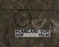
The earliest type of navigation modeled in X-Plane for iPad/X-Plane HDEF 4G is based on VOR signals (that is, signals from a very high frequency omnidirectional range transmitter). VOR transmitters work by sending a series of 360 discrete little carrier tones on a main frequency. Each of these carriers is oriented along a different radial from the station, one of 360 just like on a compass rose. Thus, when one is flying along and tunes in the main VOR frequency, one then fine tunes the navigation display to tell which of the 360 radials the aircraft is flying and also whether the transmitter station is in front of or behind the plane.
In X-Plane for iPad/X-Plane HDEF 4G, a VOR beacon is labeled as in the following image.
iPad/X-Plane HDEF 4GのためにX-Planeでモデル化されるナビゲーションで最も初期のタイプは、VOR信号に基づいています(つまり、非常に高い周波数の無指向性の範囲の送信機からの信号である)。 VOR送信機は、メイン周波数に360離散小さなキャリア一連のトーンを送信することによって動作します。これらのキャリアの各々は、わずかに上昇したコンパスのようなステーション、360の異なる半径方向に沿って配向される。このように、1はメインVOR周波数、航空機は送信局が目の前に飛行機の後ろにあるかどうかにも飛んでされている360ラジアルのどの伝えるために1、その後微調整ナビゲーション表示に沿って曲飛んでいるとき。
iPad/X-Plane HDEF 4GのためのX-Planeでは、VORビーコンは、以下の画像のようにラベル付けされている。
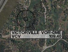
A specific type of VOR, a VOR-DME, combines the lateral guidance (that is, guidance left and right) of a VOR with the distance guidance of a DME (distance measuring equipment). In X-Plane, this is labeled as in the following image.
VOR、VOR-DME、特定のタイプは、DME(距離測定装置)の距離ガイダンスVORの横方向のガイダンスを(そう、ガイダンス左で)組み合わせたものです。 Xプレーンでは、これは、次の画像のように標識される。
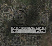
Another type of VOR beacon, a VORTAC, is also found throughout the X-Plane maps. This is a transmitter that combines both VOR and TACAN features. TACAN (or tactical air navigation) provides special information to military pilots similar to a civilian VOR. However, for our purposes, this is functionally identical to a VOR-DME. A VORTAC in X-Plane is labeled as in the following image.
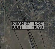
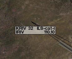
A LOC (or localizer) transmitter provides guidance to the centerline of a runway. It works by sending out two signals on the same channel, one of which modulates at 90 Hz and the other of which modulates at 150 Hz. One of these signals is sent out slightly to the left of the runway, while the other sent out slightly to the right of it. If an aircraft is picking up more of the tone modulated at 150 Hz, it is off to the left. If it is picking up more of the tone modulated at 90 Hz, it is off to the right. The course deviation indicator (or CDI) in the instrument panel then indicates this so that the pilot can correct it. When both tones are being received in equal amounts, the craft is lined up with the physical centerline of the runway. In X-Plane, a LOC transmitter is marked as in the following image.
An ILS (or instrument landing system) combines the functionality of a localizer, which provides lateral guidance, with a glideslope transmitter, which provides vertical guidance to the runway. The glideslope beacon functions similarly to the localizer, sending out two tones that have the same frequency, but different modulations. The difference is that the glideslope tells the plane that it is either too high or too low for its distance from the runway. The pilot uses this information to push the craft's nose up or down as needed. The ILS will allow a pilot to fly on instruments only to a point that is a half mile from the end of the runway at 200 feet (depending on the category of the ILS) above the ground. If the runway cannot be clearly seen at that point the pilot is prevented from executing a normal landing. If this happens, the pilot in real life is required to fly a "missed approach" and climb back to altitude in order to try again or go somewhere else.
In X-Plane, an ILS transmitter is marked as in the following image.
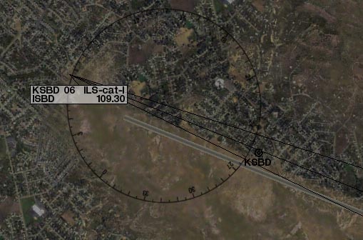
For our example approach, we’ll be flying into San Bernardino International Airport (KSBD, found in the Southern California region). Zooming into the map screen near this airport shows that the ILS signal is coming from runway 06 (as seen in the following image). Not coincidentally, there is a button here in the map screen to put the aircraft on a final approach to this runway. As seen in the following screenshot, the frequency we need to tune for KSBD's runway 06 ILS is 109.30.
今回のサンプルのアプローチのために、我々はサンバーナーディーノ国際空港(南カリフォルニア地域で発見KSBD、)に飛んでいきます。この空港の地図を表示する画面を拡大すると(次の図を参照)のILS信号は滑走路06から来ていることを示しています。偶然ではなく、ボタンを押すと、この滑走路への最終アプローチに航空機を置くために、マップ画面で、ここがあります。次のスクリーンショットに見られるように、周波数が我々はKSBDの滑走路06のILSのためのチューニングする必要が109.30である。
Navigation Instruments(ナビゲーション機器)
Before we begin the approach, let’s review the instruments used in navigation. This section assumes familiarity with the panel view as described in Chapter 2: Getting Acquainted with the iPad/iPhone 4G Simulator.
我々がアプローチを開始する前に、ナビゲーションにおいて使われる機器を見てみましょう。このセクションは、第2章:iPad/iPhone 4Gシミュレーターで説明したように、パネルビューに精通していることを前提としています。Chapter 2: Getting Acquainted with the iPad/iPhone 4G Simulator.
Instruments in the Steam Gauge Panel(蒸気圧力計パネルの機器)
The image above is the panel view in the Cessna 172. The course deviation indicator (or CDI—the most important instrument in navigating approaches like this) is seen in the following image.
上の画像は、セスナ172のパネル表示です。コース逸脱指標(またはCDIーこのようにアプローチをするときの最も重要な機器)は、以下の画像で見られます。
CDI:コース偏向指示器
The vertical line in the instrument displays the aircraft's lateral position relative to the tuned signal, and the horizontal line represents its position relative to the transmitted glidepath (where available).
To navigate using any of the previously listed NAVAIDs (VOR, LOC, ILS, etc.), that NAVAID's frequency must first be tuned in to one of the navigation radios.
The two knobs on each radio are used to tune them.
The knob on the left is used to tune the integer (or "counting number") portion of the frequency. The knob on the right is used to tune the decimal portion of the frequency.
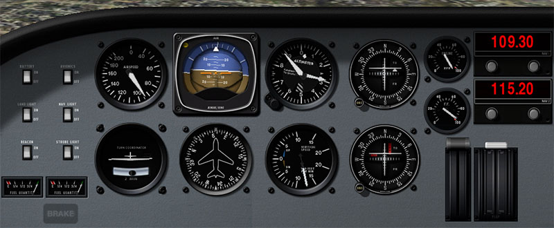
For instance, let's pretend we want to fly the ILS into San Bernardino International airport using the radio below.
機器内の垂直線は、調整された信号と比較して、航空機の横の位置を示します、そして、水平線は送信されたグライドパスと比較してその位置を表します(利用可能なところつまり、信号が出ているところ)。
以前に記載されたNAVAIDs(VOR、LOC、ILSなど)のどれかを使用してナビゲートするために、最初に、ナビゲーションラジオの1つにそのNAVAIDの周波数の波長を合わせなければなりません。各ラジオの上の2個のノブが、それらを調整するのに使用されます。
左のノブは、周波数の整数(または「カウント数」)部分を調整するのに使用されます。右側のノブは周波数の小数部分を調整するのに使用されます。
例えば、以下の無線を使用して「サンバーナーディーノ国際空港」にILSで着陸するとしましょう。
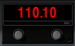
We found above that the KSBD ILS is transmitting at 109.30 Hz.
To tune the radio down to 109.30 Hz, first touch the left knob and slowly move your finger counter-clockwise until the radio reads 109.10. From here, touch the right knob and move your finger clockwise around it, bringing the frequency up to the required 109.30. At this point, we are all set to fly San Bernardino International's ILS.
Note that it doesn’t matter which NAV radio is used, so long as you follow the proper radio when flying.
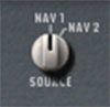
In aircraft with a source select switch, the CDI will be driven with the signal from the radio indicated by the switch.
For instance, if the source select switch was set as in the following image, the NAV 1 radio would drive the CDI.
In aircraft without a source select switch, the NAV 1 radio drives the top CDI, while the NAV 2 radio drives the bottom CDI; following the right radio is a matter of following the right CDI.
私たちは、KSBD ILSは109.30 Hzで送信していることを上記で確認した。
ラジオで109.30 Hzまで下げてチューニングするには、まず左のノブに触れ、ゆっくりとラジオが109.10を読み取るまで指を反時計回りに移動します。次は、右のつまみに触れて、必要な109.30に周波数を合わせるよう、指を時計回りに移動します。この時点で、すべてのサンバーナーディーノインターナショナルのILSを飛ぶように設定されています。
それは長い間飛行しているときに、適切なラジオに従う限り、どのNAV無線機が使用されているかは、重要ではないことに注意してください。
ソース選択スイッチのある航空機では、CDIはスイッチによって示される電波からの信号で運転されます。
例えば、選んだソースのスイッチが以下のイメージのように設定されている場合、NAV1ラジオはCDIを運転するでしょう。
選んだソースのスイッチがない航空機では、NAV1ラジオは最高CDIで運転します。そのい一方でNAV2ラジオは下部CDIで運転します。 正しいラジオに続くことは正しいCDIに続く問題です。
With the navigation radio set, assuming we are on an approach to the ILS we just tuned (which can be done using the KSBD 06 Final button found on the Map screen), the CDI should begin to move.
For instance, in the following image, the vertical bar of the CDI instrument is a bit to the right of center.
This indicates that the aircraft has moved to the left of the localizer course (recall that the localizer portion of the ILS is responsible for guiding the craft left and right).
To get back on course, the aircraft needs to turn right—in other words, it needs to follow the line on the CDI.
ナビゲーション・ラジオをセットして、調整したILSへのアプローチに我々がいるならば、CDIは動き始めなければなりません。(Mapスクリーンで見つかるKSBD 06決勝のボタンを使用して行うことができます)
例えば、次の画像では、CDI機器の垂直バーは、中央の右側にあるビットです。これは航空機が(ILSのローカライザ部分が残ってクラフトをガイドし、右の責任であることを思い出してください)ローカライザーコースの左側に移動したことを示す。背中コースで取得するには、航空機は、右に回転さつまり、それは、CDI上に線をたどる必要がある必要があります。ナビゲーションラジオセット、我々は我々だけで(地図画面上で見られるKSBD06決勝のボタンを使用して行うことができます)調整されたILSへのアプローチであると仮定して、CDIは移動を開始する必要があります。
例えば、次の画像では、CDI機器の垂直バーは、中央の右側にあるビットです。
これは航空機がローカライザーコースの左側に移動したことを示す(ILSのlocalizer部分が航空機の左右を導く役割を果たすことを思い出してください)。
コースに乗るために、航空機は、右になる必要がありますー 言い換えれば、それは、CDI上の線をたどる必要があります。

Also note the horizontal bar in the instrument. This is the glideslope indicator. In the image above, it is a bit above the center of its range. In order to stay on the glideslope, the aircraft will need to pull its nose up just a bit—in other words, it needs to follow the glideslope indicator. When the horizontal line is in the center of the instrument, the craft is right on course.
また、機器の水平バーに注意してください。これはグライドスロープインジケータです。上の画像では、それは少しその範囲の中心を超えています。グライドスロープに滞在するためには、航空機だけでつまりビットで、その機首をプルアップする必要がありますが、それはグライドスロープインジケータをたどる必要がある。水平線は、測定器の中心にあるときは、クラフトは右コースである。
Instruments in the Glass Cockpit Panel(ガラスのコックピット制御盤の器具)
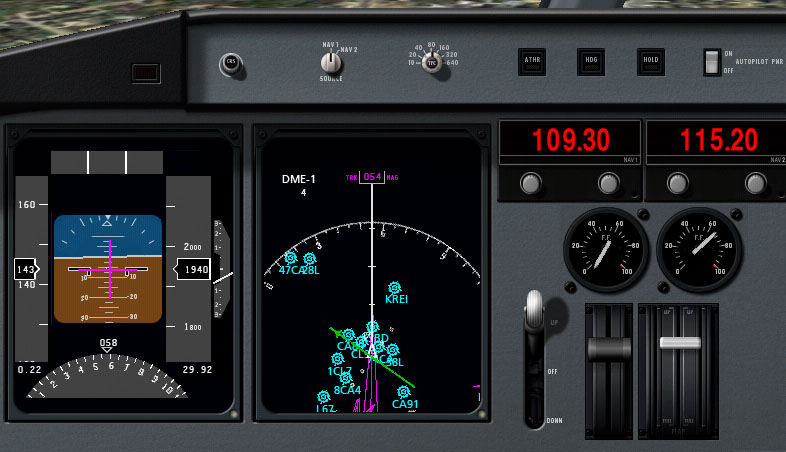
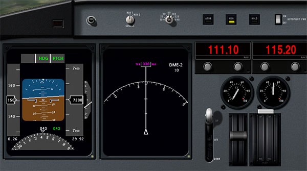
The image above shows the relevant portion of the panel found in the Cirrus Vision. Recall that the LCD panel on the left, the primary flight display, indicates the craft's pitch and roll attitude. In addition, it combines in functionality from the horizontal situation indicator, or HSI. For our purposes, the HSI serves the same function as the CDI in the steam gauge panel; it simply displays the information differently. Let's look at this screen closer.
上の画像は、シーラス·ビジョンで見つかったパネルの関連部分を示している。左、主フライトディスプレイのLCDパネルは、クラフトのピッチとロールの姿勢を示していることを思い出してください。また、水平状況の評価、またはHSIから機能的に組み合わせる。我々の目的のために、HSIは蒸気ゲージパネル内のCDIと同じ機能を提供しています、それは単に異なった情報が表示されます。それでは近いこの画面を見てみましょう。
The course deviation indicator (CDI) portion of the HSI is represented by the vertical purple line in the image above. It is in the center of the artificial horizon, meaning that the aircraft is lined up almost perfectly with the physical centerline of the runway. The glideslope indicator portion of the HSI is represented by the horizontal purple line. In the previous image, this is lined up almost perfectly with the aircraft's attitude indicator. Follow these purple lines just like the white lines in the steam gauge CDI. If the horizontal line is above the craft attitude indicator, pull up to meet it, and if the vertical line is to the left of the artificial horizon center, turn left to meet it, and so on.
Below the attitude indicator is the directional gyro. This, like the CDI and glideslope indicator, is normally a part of the HSI.
The directional gyro works like a compass in that it indicates the aircraft's heading. For instance, in the previous image, the craft has a heading of 058 (notice that the arrow is pointing just a little to the left of the six, representing a heading of 060).
If we looked at a navigational chart for San Bernardino International Airport (or use an airport database like AirNav), we would see that runway 06 that we're flying into has a magnetic heading of 057. This means that, according to the previous image, we are pointed one degree to the right of the runway.
Now let's look at the moving map.
HSIのコースの乖離指標( CDI )の部分は、上の画像の縦の紫色の線で表されている。これは、航空機が滑走路の物理的な中心線とほぼ完璧にラインアップしています。つまり、人工的な水平線の中央にある。 HSIのグライドスロープインジケータ部は、水平紫色の線で表されている。前の画像では、これは機体の姿勢インジケータにほぼ完全に並んでいます。ちょうど蒸気ゲージCDIの白いラインのように、これらの紫色のラインに従ってください。水平線は、クラフト姿勢指標を超えている場合、その上でそれを満たすためにプルアップし、縦線は人工水平センターの左側にある場合は、それを満たすために左折します。
姿勢指示器の下に方向性のジャイロです。これは、 CDIとグライドスロープの指標のように、通常は、HSIの一部です。
方向性のジャイロは航空機の見出しを示していることにあるコンパスのように動作します。例えば、前の画像では、クラフト058の機首を(矢印は060の機首を表す、 6の左側に少しだけを指していることに注意してください)があります。
我々はサンバーナーディーノ国際空港のナビゲーション·チャート(またはAirNavのような空港のデータベースを使用する)を見ると、我々は057の磁気方位を持つに私たちは飛んでいるという滑走路06を見ること。これは、前の画像によると、我々は、滑走路の右側に1度を指摘している、ということです。
今度は、移動マップを見てみましょう。
In the image above, the omni-bearing selector, which serves the same function as the OBS in the mechanical CDI instrument, is marked with a 1.
上の画像では、機械的なCDI機器におけるOBSと同じ機能を提供しています。オムニ·ベアリング·セレクタは、 1でマークされます。
In this case, it will rotate the green CDI found in the moving map to line up with whatever heading the pilot specifies—for our example approach to San Bernardino International, we would want it pointing a little to the left of the 6 found at the top of the map (for a heading of 057).
この場合には、それはパイロットが指定する機首が何と整列するように、移動マップで見られる緑のCDIを回転しますーサンバーナーディーノ・インターナショナルのアプローチのために、私たちは、それが地図の先端で見つけられた6の左に少し向けて欲しいと思うでしょう。( 057の機首方向のための)。
To the right of that is the navigation source select switch (marked with a 2 in the previous image), which switches between using the NAV 1 and NAV 2 radios. Data from the radio selected here gets sent to the EFIS. Tap this switch to change its position.
その右には、ナビゲーションのソースを選ぶスイッチがあり(前の図2で示す)、NAV1とNAV2を使用してラジオを切り換えます。ここで選択された無線機からのデータはEFISに送信されます。その位置を切り替えるには、このスイッチをタップします。
To the right of the source select switch is the zoom dial for the moving map, marked with a 3 in the image above. To move this, touch it and move your finger in a circle around it. Turn it clockwise to zoom out, and counter-clockwise to zoom in.
上の画像で、移動マップのソース選択スイッチの右にあるある3でマークされたズームダイヤルがある。これを動かすために、それに触れて、それのまわりで円形にあなたの指を動かしてください。ズームアウトするには時計回りに回して、ズームインするには反時計回りにそれを回します。
In the previous screenshot, the panel's moving map is marked with a 4. The green bar on this map indicates the aircraft's lateral position relative to the localizer's transmitted path.
When the broken center portion of the bar is moved to the left, the aircraft needs to turn left in order to stay on the path, and when it is moved to the right, the craft needs to turn right.
以前のスクリーンショットでは、パネルの移動マップが4でマークされている。このマップ上の緑のバーは、ローカライザーの送信されたパスからの相対航空機の横方向の位置を示している。
バーの途切れ途切れの中心部が左へ移動されるとき、航空機は経路でとどまるために左へ曲がる必要があります、そして、それが右へ移動されるとき、航空機は右へ曲がる必要があります。
Important to note are the light blue airports indicated in this map (for example, KSBD, CL95, and 74CA from the previous image). The locations of these airports are shown relative to the aircraft, which is represented as the white triangle in the center of the map.
この地図で示されるライトブルーの空港は、メモにとって重要です(例えば、前の画像からKSBD 、 CL95 、及び74CA ) 。これらの空港の位置は航空機と比較して示されます。そして、それは地図の中央の白い三角形として描写されます。
Localizers are represented on the moving map as purple triangles for pilots to fly down. Recall from prior in this chapter that a localizer provides the lateral (left and right) guidance in an instrument landing system (ILS).
ローカライザは、パイロットがダウンして飛行するための紫色の三角形などの移動マップ上に表現されます。ローカライザーは、計器着陸装置( ILS )横(左右)のガイダンスを提供し、この章の前のことを思い出してください。
When flying a localizer, the pilot starts at the widest part of these purple triangles.
ローカライザー飛行する際、パイロットはこれらの紫色の三角形の最も広い部分から始まります。
The center line of the triangle is the desired course and the right and left edges correspond to full scale right and left deflections of the course deviation indicator.
三角形の中心線は望ましいコースです、そして、左右の端は、コース逸脱インジケーターの左右の実物大の偏向に対応しています。
This means that the triangle’s edges represent the width that one could fly to either side of the CDI's center line and still get accurate guidance.
これは、三角形の辺が1のCDIの中心線の両側に飛んで、まだ正確な指針を得ることができる幅を表していることを意味します。
The path comes to a point at the end of the approach (corresponding to the end of the runway). Consequently, it gets much more difficult to stay on course at the end of the approach because a very small deviation off course will give the pilot a full scale deflection on the CDI.
パスは(滑走路の端部に対応する)のアプローチの最後にポイントになる。その結果、非常に小さな偏差がコースを外れ、パイロットのCDIでフルスケールの振れを与えるためのアプローチの最後にコースに滞在する多くの困難になる。
So, pilots fly into the fat part of the arrow and, hopefully, right down the center line, keeping the CDI centered the whole time by making progressively smaller and smaller corrections left and right to keep the needle centered.
だから、パイロットは、CDIが徐々に小さくしてより小さな修正が左と中心に針を維持する権利行うことで、全体の時間を中心に保ち、右、センターラインの下、うまくいけば、矢印の脂肪部分に飛ぶと。
As the navigation radios work identically in all the instrument panels, we will not describe them again here.
ナビゲーションラジオは、すべてのインストルメントパネルに同じように動作し、我々はここで再度説明しません。
Flying the Approach(アプローチフライング)
Now that we've discussed the different types of NAVAIDs in X-Plane, as well as how to use the navigation instruments in all the aircraft, let's begin flying the actual approach.
For our example instrument approach, we'll be flying into San Bernardino International Airport (KSBD), which is found in the northern half of the Southern California region. According to the map (shown in the following image), KSBD has an ILS navigation system. This means that an instrument approach to the airport can take advantage of both horizontal (left and right) and vertical (up and down) guidance, thanks to the ILS's localizer and glideslope beacon, respectively. The map shows that the ILS frequency for runway 06 is 109.30.
今、私たちは全ての航空機でのナビゲーションの機器を使用するにはどのように異なるX-Planeにおける航法援助の種類だけでなく、議論できたので、実際的なアプローチを飛んでから始めましょう。
今回の例の計器進入のために、我々は南カリフォルニア地域の北半分で発見されたサンバーナーディーノ国際空港(KSBD)に飛んで行きます。 (次の図)マップによると、KSBDはILSのナビゲーションシステムを持っています。これは、空港への計器進入は、それぞれ、指導(上下)の両方(左右)水平および垂直のILSのローカライザとグライドスロープビーコンのおかげで活用できることを意味します。マップは、滑走路06のためのILS周波数は109.30であることを示している。
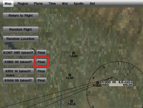
For simplicity's sake, rather than taking off from one airport and flying to San Bernardino, press the Final button for KSBD runway 06 (marked with a red box in the image above).
Now that we're on the approach, select the instrument panel view.
Tune one of the navigation radios to the desired ILS frequency (in this case, 109.30).
Make sure that the radio that was tuned is also selected with the navigation source selector switch. For instance, if the NAV 1 radio is tuned to 109.30, the source selector also needs to be pointing to NAV 1.
In the real world, we would look at a approach plate to determine what heading we should be flying to get to the runway.
As not everyone has a set of California approach plates, the AirNav database can be consulted for the heading.
Scrolling down on that web page to the Runway Information section reveals that Runway 06 has a magnetic heading of 057.
説明を簡単にするために、1つの空港から離陸して、サンバーナーディーノへ飛ぶよりはむしろ、KSBD滑走路06の最終的なボタン(上の画像の赤のボックスでマーク)を押してください。
今、我々はアプローチしようとしているので、インストルメント(機器)パネルビューを選択してください。
ナビゲーションラジオの1台を必要なILS周波数(この場合、109.30)に合わせてください。
チューニングされたラジオが、ナビゲーションソースセレクタスイッチで選択されていることを確認してください。
例えば、NAV 1無線機が109.30に同調されている場合、ソースセレクタは、NAV1を示す必要があります。
現実の世界で、滑走路に到達するためにどんな方向に飛んでいなければならないかについて決定するために、アプローチプレートを見ます。
カリフォルニアのアプローチプレートのセットがあるように、 誰もがAirNav database で、見出しのために相談することができます。
Runway Informationセクションで、そのWebページを下にスクロールすると、滑走路06が057の磁気方位を持っていることがわかります。
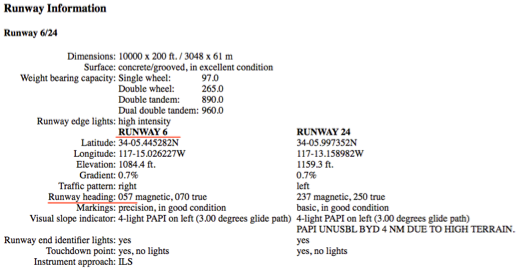
Additionally, the page lists the runway's elevation as 1084.6 feet above sea level. This information will be important when we get close to the runway, for obvious reasons!
At this point, the vertical bar in the CDI will begin to wander left or right to indicate which direction the craft needs to move in order to point down the centerline of the runway. Aim toward the deflection to intercept the localizer course; when the CDI wanders right, point the aircraft's nose right, and so on.
Additionally, the glideslope indicator (the horizontal bar in the CDI or EFIS) will begin to move.
If its needles are above the center of the instrument then the craft needs to fly up, and if they are below the center of the instrument, it needs to fly down to intercept the glideslope.
The goal is to keep the localizer bar in the CDI centered to stay on the localizer, and the glideslope bar centered to stay on the glideslope.
また、ページが1084.6フィート海抜として滑走路の高さを示しています。我々は滑走路に近づくと、この情報は、明らかに重要です!
この時点で、 CDIの垂直バーは、航空機が滑走路の中心線を指すためにどの方向に動かす必要があるかについて示すために、左または右を動き回り始めます。
ローカライザーコースをインターセプト(さえぎる)方向に向かって目指してください。 CDIが右にさまようとき、航空機の機首を右にポイントするなど。
さらに、グライドスロープインジケータ( CDIまたはEFISの水平バー)は移動を開始します。
その針が機器の中心より上にあるならば、航空機は上昇する必要があります。そして、それらが機器の中心より下にあるならば、それはグライドスロープをインターセプト(遮るように)するために下降する必要があります。
目標は、ローカライザーに滞在する中心としたCDIにおけるローカライザーバー、グライドスロープを中心としたグライドスロープバーに留まるよう維持することです。
たとえば、次の図では、 CDIが及びグライドスロープ指標は(航空機が鼻ビットを調達する必要があることを示す)ビット高い(クラフト右に回す必要があることを示す)を右に少し偏向される。
For example, in the following image, the CDI is deflected a little to the right (indicating the craft needs to turn to the right) and the glideslope indicators are a bit high (indicating that the aircraft needs to raise its nose a bit).
たとえば、次の図では、CDIは少し右に偏っている(航空機が右の方を向く必要があることを示す)、そしてグライドスロープ指標は少し高いです(航空機がその機首を少し上げる必要があることを示す)。
In the following image, the CDI is deflected to the right (indicating the aircraft needs to bank to the right) and the glideslope indicator is high (indicating the craft needs to raise its nose).
次の図では、CDIは右に偏向(航空機を右にバンクする必要があります)、そしてグライドスロープインジケータが高い(航空機がその機首を少し上げる必要があることを示す)。
Follow the guidance of the localizer and glideslope until the craft reaches an altitude of about 300 feet above the runway.
Remember from when we looked up the runway information on AirNav that its elevation is 1084.6 feet; therefore, our key altitude will be 1385 feet.
When the aircraft's altimeter reads 1385, we should switch to visual navigation to land.
At this point, if everything was done correctly, the runway will be right in front of the aircraft.
If the landing itself was managed properly, the aircraft will be at its stalling speed plus 30% with the gear and flaps down (remember that gear, flaps, and throttle are still visible in the panel view) as it comes in for a landing.
In the Cirrus Vision, this is about 90 knots. In the Cessna 172, it's about 65 knots, and in the Boeing 747, it's about 140 knots.
航空機は、滑走路の上空、約300フィートの高度に下がるまでローカライザーとグライドスロープの指示に従ってください。
我々は、その標高が1084.6フィートであることAirNav上の滑走路の情報を見ていたときから、知っています。従って、我々の高度は1385フィートになります。
航空機の高度計が1385を読み取ると、私たちは、着陸するために視覚ナビゲーションに切り替えなければなりません。
すべてが正しく行われていた場合は、この時点では、滑走路はまさしく航空機の正面にあるでしょう。
着陸自体が適切に管理されていた場合、航空機が失速速度にあります、従って着陸をするにあたって、ギヤとフラップを30%ダウンします。(ギア、フラップとスロットルがまだパネル表示で見えるのを忘れないで)。
シーラス·ビジョンでは、これは約90ノットである。セスナ172で、それは約65ノットだし、ボーイング747で、それは約140ノットです。
Using the Autopilot
The autopilot is one of the most asked about features in X-Plane—indeed, in real world planes, too. The fact is that many real aircraft owners never take the time to learn to use their autopilots. The basic autopilot functions available in X-Plane for iPad/X-Plane HDEF 4G, however, are really not too difficult to understand once the user has taken the time to learn about them.
In a real aircraft, there are three levels of autopilot functionality:
X-Plane for iPad/X-Plane HDEF 4G does not have this flight director mode. Therefore, whenever the autopilot is switched on (using the switch at the top of the panel view, highlighted in the following image), it will automatically take control of the flight controls.
Aircraft with Autopilots(オートパイロットと航空機)
The following aircraft have autopilot functions:
以下の航空機は自動操縦の機能があります。
Available Autopilot Functions(利用可能な自動操縦機能)
The following autopilot functions are available in the aircraft listed above.
次の自動操縦機能は、上記の航空機内で使用可能です。
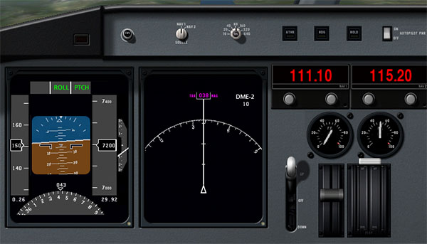
ROLL and PTCH(ROLLとPTCH)
The first autopilot functions, ROLL and PTCH, are the roll and pitch hold modes, respectively. When the autopilot is switched on, these two are turned on automatically.
They will hold the current roll and pitch attitudes of the aircraft.
For example, if the craft has its nose pitched down ten degrees and is in a five degree left bank when the autopilot is switched on, ROLL and PTCH modes will hold this ten degree down, five degree left attitude.
These modes are shown in the following image.
最初の自動操縦機能、ROLLとPTCHは、それぞれのロールとピッチホールドモードです。オートパイロットをオンにすると、これら二つは自動的にオンになる。それらは、航空機の現在(飛んでいるその時)のロールとピッチ姿勢を保持します。
例えば、航空機は自動操縦装置がオンにされたときに、その機首が10度ピッチダウンしており、5度、左に傾いている場合は、ROLLとPTCHモードはこの姿勢を制御するため、10度と5度を抑制して抑えます。
これらのモードは、次の図に示します。一番上の右端がオートパイロットのスイッチ。
ATHR(オートスロットル)
The next autopilot function is the auto-throttle mode.
When the ATHR button is pressed, the autopilot will attempt to maintain the craft's current airspeed by increasing or decreasing the throttle.
It will not, however, attempt to control the craft's speed using any other method, such as pitching the nose up or down or adding or subtracting flaps.
Therefore, the auto-throttle will be able to put the throttle anywhere between its maximum or minimum, but it will not be able to maintain an excessively high or low airspeed (such as one obtained by pitching the nose excessively low or high).
The ATHR is turned on (as indicated by its button being lit yellow) in the following image.
次のオートパイロット機能は、オートスロットルモードです。
ATHRボタンが押されると、オートパイロットは、スロットルを増加または減少させることによって飛行機の現在の対気速度を維持しようとします。
しかしながら、これはそのような機首のピッチングをフラップを加算または減算などの任意の他の方法を用いて航空機の速度を制御しようとしない。
そのため、オートスロットルはどこでも、その最大値または最小値との間にスロットルを入れることができるようになりますが、それは、過度に高いまたは低い対気速度の場合は維持することができません(そのような機首が過度に低いか、高いピッチング状態の場合)。
ATHRは次の図(そのボタンが黄色に点灯されることによって示されているように)オンになっている。上段の中央の四角のスイッチ(黄色がON)で左下の機器の上に「THRO」と緑色で表示される。
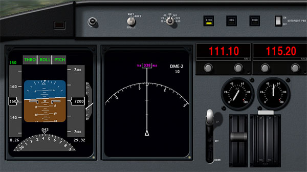
In the image above, the auto-throttle is set to hold 150 knots. Note that it is not uncommon for the auto-throttle to stay a few knots above or below the set speed like this.
With the ATHR button pressed, the other autopilot functions can be disengaged by turning the autopilot power switch to off. This allows the pilot to pitch and roll the craft freely while the auto-throttle maintains the same speed.
Also, note that when auto-throttle mode is engaged, it will start the throttle at its minimum, then slowly bring the throttle up to the point where it holds the selected airspeed. This results in a drop of around ten knots when the ATHR button is first pressed, but this drop in speed is not permanent.
上の画像では、オートスロットルは150ノットを保持するために設定されています。オートスロットルはこのような設定速度の上または下、いくつかの結び目に滞在することは珍しいことではないことに注意してください。
ATHRボタンを押すことで、autopilot power スイッチをOFFにすることによって、他の自動操縦機能をはずすことができます。これは、パイロットがピッチと自動スロットルが同じ速度を維持しながら、自由に航空機をロールバック(元に戻す)することができます。
また、オートスロットルモードの締結時に、それはゆっくりと、それが選択された対気速度を保持しているポイントにスロットルを開き、その最小スロットルを開始することに注意してください。これはATHRボタンを最初に押して約10ノットの低下をもたらしたが、この速度の低下は永続的ではありません。
HDG(機首方向)
The next autopilot function is the heading hold mode. Pressing the HDG button will set the autopilot to follow the heading currently displayed on the directional gyro (recall that the directional gyro is the partial circle found at the bottom of the left EFIS display). It will follow this heading by rolling the aircraft left and right. For this reason, when the HDG button is pressed, heading hold mode will replace roll hold mode.
For instance, in the following image, the HDG button was pressed when the craft was pointed at heading 043. Since a heading of 0 is due north, and a heading of 090 is due east, the autopilot will be flying the aircraft northeast.
次のオートパイロット機能がヘディングホールドモードである。(上段の右から3番目のボタン、黄色でON)
HDGボタンを押すと、ジャイロで表示された現在方向の機首をフォローして自動操縦を設定します(方向ジャイロの左EFISディスプレイの下部にある部分円)。これは、航空機を左右にならすことにより、この機首の方向を決めます。 HDGボタンを押したときに、このような理由から、ヘディングホールドモードは、ロール·ホールド·モードに置き換えられます。
たとえば次の図で、航空機の機首が043に向けられたとき、HDGボタンが押されました。0の機首が真北である、そして、090の見出しが真東であるので、自動操縦は航空機北東を飛んでいます。
後ろの言葉の意味が全く理解できない。0の機首が真北って何?
HOLD(高度)
The final autopilot function is the altitude hold. Pressing the HOLD button will cause the autopilot to hold the current altitude by pitching the nose up or down. This mode automatically replaces pitch hold mode.
For instance, in the following screenshot, the HOLD button was pressed when the craft was at an altitude of 7,200 feet, so the autopilot will continue to maintain this altitude.
最終的なオートパイロット機能は、高度ホールドです。 HOLDボタンを押すと、自動操縦装置が上下に機首をピッチングして、現在の高度を保持することになります。このモードでは、自動的にピッチホールド·モードに置き換えられます。
たとえば、次のスクリーンショットに、HOLDボタンはクラフトは7200フィートの高度でいた時に押されたため、自動操縦は、この高度を維持していきます。

Taking Off from and Landing on a Carrier(航空母艦から離陸して、それに着陸すること)
Carrier operations are another challenging and fun feature of X-Plane for iPad and X-Plane HDEF 4G.
To take off from a carrier, a few things must be done in quick succession. First, the throttle slider must be dragged to the top of its range of motion. The flaps must be pulled down about half way, and the BRAKE button must be tapped to disengage the brakes and activate the catapult propelling the craft off the deck. From there, simply guide the craft down the flight deck and, once clear, pull the nose up sharply and bring the gear up.
(Note that information on the location of the these controls on the screen can be found in Chapter 2.)
Landing on the carrier is a bit more difficult. First, note that the ADF (the arrow in the middle of the direction gyro, which is highlighted in the following image) always points the way back to the carrier. This is invaluable in setting up an approach to the carrier.
航空母艦操作は、X-PlaneのiPadとX-Plane HDEF 4Gのための別の挑戦的で楽しい機能です。
航空母艦から離陸し、いくつかのことが立て続けに行われなければならない。まず、スロットルスライダはその稼働範囲の一番上にドラッグする必要があります。フラップは約半分プルダウンする必要があり、ブレーキボタンからブレーキを外し、デッキオフクラフトを推進カタパルトをアクティブにするためにタップする必要があります。そこから、単純に飛行甲板下の工芸品を導き、一度クリア、シャープに鼻を引き上げてギアアップをもたらします。
(画面上でこれらのコントロールの位置は、第2章に記載されています上の情報に注意してください。)
キャリア上に着陸することは少し難しくなります。まず、ADF(以下の画像で強調表示された方向のジャイロの真ん中の矢印)がいつでも戻っキャリアへの道を指していることに注意してください。これは、キャリアへのアプローチを設定する際に非常に貴重です。

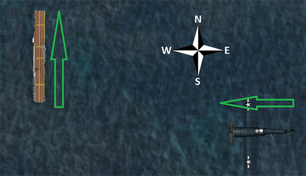
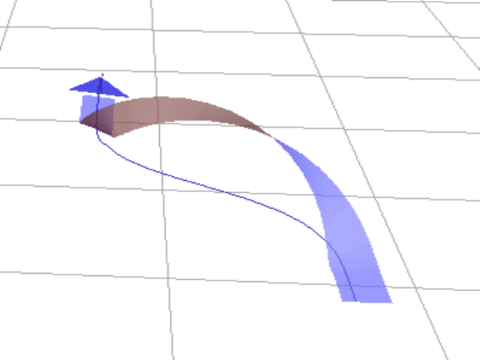
To set up an approach to the WWII carrier used with the F4U (whose landing deck goes straight down the flight deck), a pilot should fly either a 90 or 45 degree intercept (depending on the aircraft's distance) in order to get behind the ship. If the ship is traveling north, and the aircraft is coming from the east with the ship to its north (as in the following diagram), the pilot will continue on his or her intercept trajectory until the ADF needle is pointing either 45 or 90 degrees to the right, at which point he or she will turn in toward the landing deck.
(その着陸甲板直線飛行甲板を下っ)F4Uで使用第二次世界大戦のキャリアへのアプローチを設定するには、パイロットは船の後ろに取得するために、いずれか90、または45度のインターセプト(航空機の距離に応じて)飛ぶ必要があります。船が北に移動している、と航空機が(次の図のように)、その北には船で東から来ている場合は、ADFの針が45度または90度のいずれかを指しているまで、パイロットは自分の傍受軌道に継続します右に、その時点で、彼または彼女は着陸デッキに向かって変わります。
If the carrier is instead the John F. Kennedy-class ship used with the F-4, F-14, and F-18, the landing runway is angled 30 degrees to the port (left) side—it is not straight down the flight deck like in the older carriers. This change was made to prevent the all-too-common overruns that occurred in WWII when a landing plane crashed into the stacked line of planes at the far end of the carrier. A pilot landing on such a carrier must correct for this angling. Using the example and diagram above, the pilot would instead wait until the ADF was pointing either 15 or 60 degrees to the right before turning in for a landing.
When approaching the flight deck to land, a glidepath of about 3.5 degrees is standard. At this time, the tail hook should be lowered by tapping the HOOK button, turning it green. This will allow the tail of the aircraft to catch the arresting wires on the deck. These wires will accelerate the craft from well over 100 knots down to zero in little more than a second.
Unlike in a conventional landing, there should be no “flare” before touching down on the carrier. Whereas, say, an airliner would raise its nose up just before touching the runway (thereby ensuring a smooth landing), a carrier approach should maintain a constant glideslope until the craft hits the deck.
Also, rather counter-intuitively, a real fighter pilot must slam the throttle to full the instant that the aircraft touches the deck. This is because, even when the pilot has done everything right, the craft's tail hook can bounce over the arresting wires in what is called a “bolter.” When this happens, the pilot must be ready to get off the deck safely and come around for another try. Don't worry—even when the throttle revs up like this, the arresting wires will still pull the craft down to zero velocity.
To see how the pros do it, check out the following links:
Video: Carrier Landing—F-4J Phantom II in the Mediterranean Sea
Video: F-14 Carrier Landing
Walkthrough: How to land a jet plane on an aircraft carrier
Combat
Combat Basics
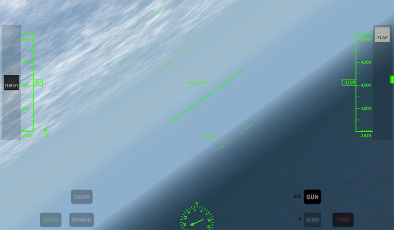
Of course, taking off and landing on the carrier are only means to an end. The real goal is the dogfight—shooting down the enemy. Each aircraft's weapons can be fired with the FIRE button (labeled 1 in the following image). Above and to the left of this button is the GUN button (labeled 2 in the following image), and beside this button is a number indicating the number of rounds left. In the MiG, F-4, F-14, and F-18, there is also an AIM9 button (labeled 3 in the following image) beneath the GUN button. Tapping this will switch from the guns to the guided missiles, and tapping the GUN button will switch back.

Using the Gun
When firing a gun, be sure to lead opponents (called deflection shooting)—fire at where they will be, not where they are. Mastering so-called “high deflection shooting” can make the difference between ending a fight quickly and losing it entirely. Whereas the surest shot will always come when a pilot is right on an enemy's tail, a high deflection shot comes from beside or in front of the enemy. In most cases, a pilot has only a split second in which the enemy will cross his or her path of fire, so timing is critical.
Using the Missiles
When firing the AIM-9 missiles, they will more or less lock on to an enemy automatically, even when fired from a good distance. While this makes it relatively easy to score a kill on an enemy, that enemy is equipped with the same missiles, so be prepared to jink (rapidly deflect the flight controls into turns in different directions) when the return fire comes.
Using the Targeting Reticle
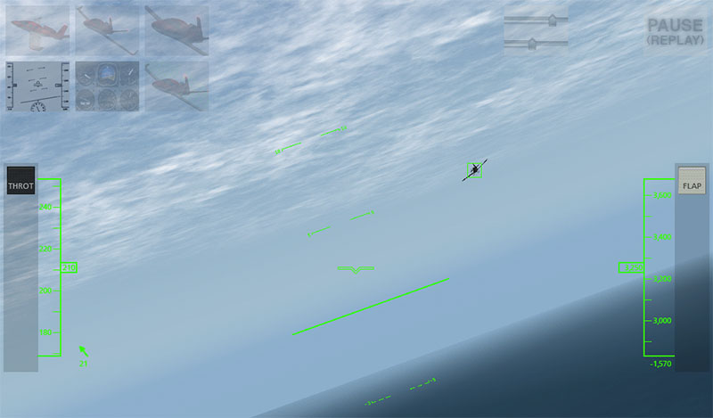
The targeting reticle always follows the enemy's aircraft. If the enemy is visible on screen (as in the following image), it will appear as a thin green box around the opponent's craft.
If, however, the enemy is not visible on screen, the reticle will be “dragged” to the edge of the screen and will appear as a thick green bar on the edge of the screen. For instance, in the following image, the opponent is on the pilot's right side (the green bar is near the center on the right side of the screen).
The reticle breaks down, though, when the opponent's aircraft is very close to the user's, or when it is directly on the user's tail. In this case, the reticle will bounce around from full left deflection to full right deflection. This is simply a limitation associated with trying to point in three dimensions using a two dimensional display.
Strategy
The key to winning a dogfight lies in creating a situation where your aircraft's strengths are emphasized and an opponent's weaknesses are exploited. This means trying to force a tight, up-close battle when flying a more maneuverable fighter than the enemy, or aiming for dive-bombs and other tactics requiring speed and weight when flying a faster, larger craft.
Additionally, do not underestimate the value of quick combat maneuvers, such as:
For more information on combat tactics, see the Dicta Boelcke, a list of tactics developed by WWI ace Oswald Boelcke.
Turning Off Combat
To disable combat when flying a fighter in X-Plane for iPad and X-Plane HDEF 4G, you can do one of two things:
To turn down the enemy’s skill level, open the Settings (by tapping the button in the upper right of the screen), go to the Set tab. Drag the skill level slider all the way down to zero. Then, return to the Map tab to return to your flight.


第6章: iPad/X-Plane HDEF 4Gの先進機能
Note: This chapter assumes prior familiarity with the workings of the view options and the Settings menu, as well as with the standard flight instruments. All of this is described in Chapter 2: Getting Acquainted with the iPad/iPhone 4G Simulator.
注意:この章では、以前のビューオプションの仕組みに精通し、[設定]メニューだけでなく、標準的な飛行計器とを前提としています。アプリ/ iPhoneの4Gシミュレータ各部の名称と働き:これのすべては、第2章で説明されている。
Contents
- Flying an Approach Using the Instrument Panel
- Types of NAVAIDs
- Navigation Instruments
- Instruments in the Steam Gauge Panel
- Instruments in the Glass Cockpit Panel
- Flying the Approach
- Using the Autopilot
- Aircraft with Autopilots
- Available Autopilot Functions
- ROLL and PTCH
- ATHR
- HDG
- HOLD
- Taking Off from and Landing on a Carrier
- Combat
- Combat Basics
- Using the Gun
- Using the Missiles
- Using the Targeting Reticle
- Strategy
- Turning Off Combat
Flying an Approach Using the Instrument Panel
インストゥルメントパネルを使用したフライングアプローチ
Nearly all of the aircraft in X-Plane for iPad/X-Plane HDEF 4G have basic navigation radios and instruments built into them, and all of these are used in more or less the same way. We will go through an example for flying an ILS approach (that is, an approach using an instrument landing system) in the Southern California region, but similar steps can be used for any airport.
Note that instrument navigation is not for the faint of heart. X-Plane is as realistic a flight simulator as possible, and navigation is no exception. This section is by no means a complete guide to airplane navigation (there are plenty of 400-page books available that claim that), but it will go into quite a bit of detail. We will discuss a great deal of side information needed to fly all approaches, but we will always come back and relate it to flying the example approach into San Bernardino International (again, found in the Southern California region).
To fly an instrument approach, users will first need to know the local navigational aid (NAVAID) frequencies. To find this, tap the center of the screen to make the various menu options appear, then open the Settings menu.
The map in the window that appears shows the ILS, LOC, VOR, and VORTAC frequencies for the area. Zoom in and out of the map by placing two fingers on the screen and dragging them farther apart (to zoom in) or closer together (to zoom out). To pan the map, place one finger on the map and drag it, and to rotate it, place two fingers onto the map and twist them in a circular motion.
Let's discuss the specifics of each of these types of navigational aids (NAVAIDs)
ほぼすべてのiPad/X-Plane HDEF 4GのためのX-Planeにおける航空機の基本的なナビゲーションは、ラジオ、それらに組み込まれた器具を有し、これらの全ては多かれ少なかれ同じように使用されている。私たちは、南カリフォルニア地域で(つまり、計器着陸装置を使用したアプローチである)のILSアプローチを飛行するための例示を通過しますが、同様の手順では、空港を使用することができます。
その機器のナビゲーションは心臓の弱い人のためではないことに注意してください。 Xプレーンは、可能な限り現実的なフライトシミュレータであり、ナビゲーションも例外ではない。このセクションでは、それは細部にかなりに入ります(そのクレーム利用可能な400ページの本がたくさんあります)決して飛行機ナビゲーションへの完全なガイドです。我々は、すべてのアプローチを飛行するのに必要なサイド情報を大量に説明しますが、我々は常に戻ってきて(再び、南カリフォルニア地域にある)サンバーナーディーノ国際への例のアプローチを飛行に関連します。
計器進入を飛行するには、ユーザーは最初にローカル航行援助( NAVAID )周波数を知っている必要があります。これを見つけるために、様々なメニューオプションは[設定]メニューを開き、表示されるように画面中央をタップします。
表示されたウィンドウ内のマップは、地域のためのILS 、 LOC 、 VORとVORTAC周波数を示しています。画面上で2本の指を置き、 (ズームアウトするために)互いに接近(拡大するには)遠く離れて、それらをドラッグするかによって中、地図のズームイン、ズームアウト。マップをパンするには、マップ上に指一本を置き、それをドラッグし、それを回転させ、マップ上に2本の指を置いて、円を描くようにそれらをねじる。
それではナビゲーション支援、これらのタイプのそれぞれの特性(航法援助を)講義しましょう
Types of NAVAIDs(航海用機器のタイプ)
The earliest type of navigation modeled in X-Plane for iPad/X-Plane HDEF 4G is based on VOR signals (that is, signals from a very high frequency omnidirectional range transmitter). VOR transmitters work by sending a series of 360 discrete little carrier tones on a main frequency. Each of these carriers is oriented along a different radial from the station, one of 360 just like on a compass rose. Thus, when one is flying along and tunes in the main VOR frequency, one then fine tunes the navigation display to tell which of the 360 radials the aircraft is flying and also whether the transmitter station is in front of or behind the plane.
In X-Plane for iPad/X-Plane HDEF 4G, a VOR beacon is labeled as in the following image.
iPad/X-Plane HDEF 4GのためにX-Planeでモデル化されるナビゲーションで最も初期のタイプは、VOR信号に基づいています(つまり、非常に高い周波数の無指向性の範囲の送信機からの信号である)。 VOR送信機は、メイン周波数に360離散小さなキャリア一連のトーンを送信することによって動作します。これらのキャリアの各々は、わずかに上昇したコンパスのようなステーション、360の異なる半径方向に沿って配向される。このように、1はメインVOR周波数、航空機は送信局が目の前に飛行機の後ろにあるかどうかにも飛んでされている360ラジアルのどの伝えるために1、その後微調整ナビゲーション表示に沿って曲飛んでいるとき。
iPad/X-Plane HDEF 4GのためのX-Planeでは、VORビーコンは、以下の画像のようにラベル付けされている。
A specific type of VOR, a VOR-DME, combines the lateral guidance (that is, guidance left and right) of a VOR with the distance guidance of a DME (distance measuring equipment). In X-Plane, this is labeled as in the following image.
VOR、VOR-DME、特定のタイプは、DME(距離測定装置)の距離ガイダンスVORの横方向のガイダンスを(そう、ガイダンス左で)組み合わせたものです。 Xプレーンでは、これは、次の画像のように標識される。
Another type of VOR beacon, a VORTAC, is also found throughout the X-Plane maps. This is a transmitter that combines both VOR and TACAN features. TACAN (or tactical air navigation) provides special information to military pilots similar to a civilian VOR. However, for our purposes, this is functionally identical to a VOR-DME. A VORTAC in X-Plane is labeled as in the following image.
A LOC (or localizer) transmitter provides guidance to the centerline of a runway. It works by sending out two signals on the same channel, one of which modulates at 90 Hz and the other of which modulates at 150 Hz. One of these signals is sent out slightly to the left of the runway, while the other sent out slightly to the right of it. If an aircraft is picking up more of the tone modulated at 150 Hz, it is off to the left. If it is picking up more of the tone modulated at 90 Hz, it is off to the right. The course deviation indicator (or CDI) in the instrument panel then indicates this so that the pilot can correct it. When both tones are being received in equal amounts, the craft is lined up with the physical centerline of the runway. In X-Plane, a LOC transmitter is marked as in the following image.
An ILS (or instrument landing system) combines the functionality of a localizer, which provides lateral guidance, with a glideslope transmitter, which provides vertical guidance to the runway. The glideslope beacon functions similarly to the localizer, sending out two tones that have the same frequency, but different modulations. The difference is that the glideslope tells the plane that it is either too high or too low for its distance from the runway. The pilot uses this information to push the craft's nose up or down as needed. The ILS will allow a pilot to fly on instruments only to a point that is a half mile from the end of the runway at 200 feet (depending on the category of the ILS) above the ground. If the runway cannot be clearly seen at that point the pilot is prevented from executing a normal landing. If this happens, the pilot in real life is required to fly a "missed approach" and climb back to altitude in order to try again or go somewhere else.
In X-Plane, an ILS transmitter is marked as in the following image.
For our example approach, we’ll be flying into San Bernardino International Airport (KSBD, found in the Southern California region). Zooming into the map screen near this airport shows that the ILS signal is coming from runway 06 (as seen in the following image). Not coincidentally, there is a button here in the map screen to put the aircraft on a final approach to this runway. As seen in the following screenshot, the frequency we need to tune for KSBD's runway 06 ILS is 109.30.
今回のサンプルのアプローチのために、我々はサンバーナーディーノ国際空港(南カリフォルニア地域で発見KSBD、)に飛んでいきます。この空港の地図を表示する画面を拡大すると(次の図を参照)のILS信号は滑走路06から来ていることを示しています。偶然ではなく、ボタンを押すと、この滑走路への最終アプローチに航空機を置くために、マップ画面で、ここがあります。次のスクリーンショットに見られるように、周波数が我々はKSBDの滑走路06のILSのためのチューニングする必要が109.30である。
Navigation Instruments(ナビゲーション機器)
Before we begin the approach, let’s review the instruments used in navigation. This section assumes familiarity with the panel view as described in Chapter 2: Getting Acquainted with the iPad/iPhone 4G Simulator.
我々がアプローチを開始する前に、ナビゲーションにおいて使われる機器を見てみましょう。このセクションは、第2章:iPad/iPhone 4Gシミュレーターで説明したように、パネルビューに精通していることを前提としています。Chapter 2: Getting Acquainted with the iPad/iPhone 4G Simulator.
Instruments in the Steam Gauge Panel(蒸気圧力計パネルの機器)
The image above is the panel view in the Cessna 172. The course deviation indicator (or CDI—the most important instrument in navigating approaches like this) is seen in the following image.
上の画像は、セスナ172のパネル表示です。コース逸脱指標(またはCDIーこのようにアプローチをするときの最も重要な機器)は、以下の画像で見られます。
CDI:コース偏向指示器
The vertical line in the instrument displays the aircraft's lateral position relative to the tuned signal, and the horizontal line represents its position relative to the transmitted glidepath (where available).
To navigate using any of the previously listed NAVAIDs (VOR, LOC, ILS, etc.), that NAVAID's frequency must first be tuned in to one of the navigation radios.
The two knobs on each radio are used to tune them.
The knob on the left is used to tune the integer (or "counting number") portion of the frequency. The knob on the right is used to tune the decimal portion of the frequency.
For instance, let's pretend we want to fly the ILS into San Bernardino International airport using the radio below.
機器内の垂直線は、調整された信号と比較して、航空機の横の位置を示します、そして、水平線は送信されたグライドパスと比較してその位置を表します(利用可能なところつまり、信号が出ているところ)。
以前に記載されたNAVAIDs(VOR、LOC、ILSなど)のどれかを使用してナビゲートするために、最初に、ナビゲーションラジオの1つにそのNAVAIDの周波数の波長を合わせなければなりません。各ラジオの上の2個のノブが、それらを調整するのに使用されます。
左のノブは、周波数の整数(または「カウント数」)部分を調整するのに使用されます。右側のノブは周波数の小数部分を調整するのに使用されます。
例えば、以下の無線を使用して「サンバーナーディーノ国際空港」にILSで着陸するとしましょう。
We found above that the KSBD ILS is transmitting at 109.30 Hz.
To tune the radio down to 109.30 Hz, first touch the left knob and slowly move your finger counter-clockwise until the radio reads 109.10. From here, touch the right knob and move your finger clockwise around it, bringing the frequency up to the required 109.30. At this point, we are all set to fly San Bernardino International's ILS.
Note that it doesn’t matter which NAV radio is used, so long as you follow the proper radio when flying.
In aircraft with a source select switch, the CDI will be driven with the signal from the radio indicated by the switch.
For instance, if the source select switch was set as in the following image, the NAV 1 radio would drive the CDI.
In aircraft without a source select switch, the NAV 1 radio drives the top CDI, while the NAV 2 radio drives the bottom CDI; following the right radio is a matter of following the right CDI.
私たちは、KSBD ILSは109.30 Hzで送信していることを上記で確認した。
ラジオで109.30 Hzまで下げてチューニングするには、まず左のノブに触れ、ゆっくりとラジオが109.10を読み取るまで指を反時計回りに移動します。次は、右のつまみに触れて、必要な109.30に周波数を合わせるよう、指を時計回りに移動します。この時点で、すべてのサンバーナーディーノインターナショナルのILSを飛ぶように設定されています。
それは長い間飛行しているときに、適切なラジオに従う限り、どのNAV無線機が使用されているかは、重要ではないことに注意してください。
ソース選択スイッチのある航空機では、CDIはスイッチによって示される電波からの信号で運転されます。
例えば、選んだソースのスイッチが以下のイメージのように設定されている場合、NAV1ラジオはCDIを運転するでしょう。
選んだソースのスイッチがない航空機では、NAV1ラジオは最高CDIで運転します。そのい一方でNAV2ラジオは下部CDIで運転します。 正しいラジオに続くことは正しいCDIに続く問題です。
With the navigation radio set, assuming we are on an approach to the ILS we just tuned (which can be done using the KSBD 06 Final button found on the Map screen), the CDI should begin to move.
For instance, in the following image, the vertical bar of the CDI instrument is a bit to the right of center.
This indicates that the aircraft has moved to the left of the localizer course (recall that the localizer portion of the ILS is responsible for guiding the craft left and right).
To get back on course, the aircraft needs to turn right—in other words, it needs to follow the line on the CDI.
ナビゲーション・ラジオをセットして、調整したILSへのアプローチに我々がいるならば、CDIは動き始めなければなりません。(Mapスクリーンで見つかるKSBD 06決勝のボタンを使用して行うことができます)
例えば、次の画像では、CDI機器の垂直バーは、中央の右側にあるビットです。これは航空機が(ILSのローカライザ部分が残ってクラフトをガイドし、右の責任であることを思い出してください)ローカライザーコースの左側に移動したことを示す。背中コースで取得するには、航空機は、右に回転さつまり、それは、CDI上に線をたどる必要がある必要があります。ナビゲーションラジオセット、我々は我々だけで(地図画面上で見られるKSBD06決勝のボタンを使用して行うことができます)調整されたILSへのアプローチであると仮定して、CDIは移動を開始する必要があります。
例えば、次の画像では、CDI機器の垂直バーは、中央の右側にあるビットです。
これは航空機がローカライザーコースの左側に移動したことを示す(ILSのlocalizer部分が航空機の左右を導く役割を果たすことを思い出してください)。
コースに乗るために、航空機は、右になる必要がありますー 言い換えれば、それは、CDI上の線をたどる必要があります。
Also note the horizontal bar in the instrument. This is the glideslope indicator. In the image above, it is a bit above the center of its range. In order to stay on the glideslope, the aircraft will need to pull its nose up just a bit—in other words, it needs to follow the glideslope indicator. When the horizontal line is in the center of the instrument, the craft is right on course.
また、機器の水平バーに注意してください。これはグライドスロープインジケータです。上の画像では、それは少しその範囲の中心を超えています。グライドスロープに滞在するためには、航空機だけでつまりビットで、その機首をプルアップする必要がありますが、それはグライドスロープインジケータをたどる必要がある。水平線は、測定器の中心にあるときは、クラフトは右コースである。
Instruments in the Glass Cockpit Panel(ガラスのコックピット制御盤の器具)
The image above shows the relevant portion of the panel found in the Cirrus Vision. Recall that the LCD panel on the left, the primary flight display, indicates the craft's pitch and roll attitude. In addition, it combines in functionality from the horizontal situation indicator, or HSI. For our purposes, the HSI serves the same function as the CDI in the steam gauge panel; it simply displays the information differently. Let's look at this screen closer.
上の画像は、シーラス·ビジョンで見つかったパネルの関連部分を示している。左、主フライトディスプレイのLCDパネルは、クラフトのピッチとロールの姿勢を示していることを思い出してください。また、水平状況の評価、またはHSIから機能的に組み合わせる。我々の目的のために、HSIは蒸気ゲージパネル内のCDIと同じ機能を提供しています、それは単に異なった情報が表示されます。それでは近いこの画面を見てみましょう。
The course deviation indicator (CDI) portion of the HSI is represented by the vertical purple line in the image above. It is in the center of the artificial horizon, meaning that the aircraft is lined up almost perfectly with the physical centerline of the runway. The glideslope indicator portion of the HSI is represented by the horizontal purple line. In the previous image, this is lined up almost perfectly with the aircraft's attitude indicator. Follow these purple lines just like the white lines in the steam gauge CDI. If the horizontal line is above the craft attitude indicator, pull up to meet it, and if the vertical line is to the left of the artificial horizon center, turn left to meet it, and so on.
Below the attitude indicator is the directional gyro. This, like the CDI and glideslope indicator, is normally a part of the HSI.
The directional gyro works like a compass in that it indicates the aircraft's heading. For instance, in the previous image, the craft has a heading of 058 (notice that the arrow is pointing just a little to the left of the six, representing a heading of 060).
If we looked at a navigational chart for San Bernardino International Airport (or use an airport database like AirNav), we would see that runway 06 that we're flying into has a magnetic heading of 057. This means that, according to the previous image, we are pointed one degree to the right of the runway.
Now let's look at the moving map.
HSIのコースの乖離指標( CDI )の部分は、上の画像の縦の紫色の線で表されている。これは、航空機が滑走路の物理的な中心線とほぼ完璧にラインアップしています。つまり、人工的な水平線の中央にある。 HSIのグライドスロープインジケータ部は、水平紫色の線で表されている。前の画像では、これは機体の姿勢インジケータにほぼ完全に並んでいます。ちょうど蒸気ゲージCDIの白いラインのように、これらの紫色のラインに従ってください。水平線は、クラフト姿勢指標を超えている場合、その上でそれを満たすためにプルアップし、縦線は人工水平センターの左側にある場合は、それを満たすために左折します。
姿勢指示器の下に方向性のジャイロです。これは、 CDIとグライドスロープの指標のように、通常は、HSIの一部です。
方向性のジャイロは航空機の見出しを示していることにあるコンパスのように動作します。例えば、前の画像では、クラフト058の機首を(矢印は060の機首を表す、 6の左側に少しだけを指していることに注意してください)があります。
我々はサンバーナーディーノ国際空港のナビゲーション·チャート(またはAirNavのような空港のデータベースを使用する)を見ると、我々は057の磁気方位を持つに私たちは飛んでいるという滑走路06を見ること。これは、前の画像によると、我々は、滑走路の右側に1度を指摘している、ということです。
今度は、移動マップを見てみましょう。
In the image above, the omni-bearing selector, which serves the same function as the OBS in the mechanical CDI instrument, is marked with a 1.
上の画像では、機械的なCDI機器におけるOBSと同じ機能を提供しています。オムニ·ベアリング·セレクタは、 1でマークされます。
In this case, it will rotate the green CDI found in the moving map to line up with whatever heading the pilot specifies—for our example approach to San Bernardino International, we would want it pointing a little to the left of the 6 found at the top of the map (for a heading of 057).
この場合には、それはパイロットが指定する機首が何と整列するように、移動マップで見られる緑のCDIを回転しますーサンバーナーディーノ・インターナショナルのアプローチのために、私たちは、それが地図の先端で見つけられた6の左に少し向けて欲しいと思うでしょう。( 057の機首方向のための)。
To the right of that is the navigation source select switch (marked with a 2 in the previous image), which switches between using the NAV 1 and NAV 2 radios. Data from the radio selected here gets sent to the EFIS. Tap this switch to change its position.
その右には、ナビゲーションのソースを選ぶスイッチがあり(前の図2で示す)、NAV1とNAV2を使用してラジオを切り換えます。ここで選択された無線機からのデータはEFISに送信されます。その位置を切り替えるには、このスイッチをタップします。
To the right of the source select switch is the zoom dial for the moving map, marked with a 3 in the image above. To move this, touch it and move your finger in a circle around it. Turn it clockwise to zoom out, and counter-clockwise to zoom in.
上の画像で、移動マップのソース選択スイッチの右にあるある3でマークされたズームダイヤルがある。これを動かすために、それに触れて、それのまわりで円形にあなたの指を動かしてください。ズームアウトするには時計回りに回して、ズームインするには反時計回りにそれを回します。
In the previous screenshot, the panel's moving map is marked with a 4. The green bar on this map indicates the aircraft's lateral position relative to the localizer's transmitted path.
When the broken center portion of the bar is moved to the left, the aircraft needs to turn left in order to stay on the path, and when it is moved to the right, the craft needs to turn right.
以前のスクリーンショットでは、パネルの移動マップが4でマークされている。このマップ上の緑のバーは、ローカライザーの送信されたパスからの相対航空機の横方向の位置を示している。
バーの途切れ途切れの中心部が左へ移動されるとき、航空機は経路でとどまるために左へ曲がる必要があります、そして、それが右へ移動されるとき、航空機は右へ曲がる必要があります。
Important to note are the light blue airports indicated in this map (for example, KSBD, CL95, and 74CA from the previous image). The locations of these airports are shown relative to the aircraft, which is represented as the white triangle in the center of the map.
この地図で示されるライトブルーの空港は、メモにとって重要です(例えば、前の画像からKSBD 、 CL95 、及び74CA ) 。これらの空港の位置は航空機と比較して示されます。そして、それは地図の中央の白い三角形として描写されます。
Localizers are represented on the moving map as purple triangles for pilots to fly down. Recall from prior in this chapter that a localizer provides the lateral (left and right) guidance in an instrument landing system (ILS).
ローカライザは、パイロットがダウンして飛行するための紫色の三角形などの移動マップ上に表現されます。ローカライザーは、計器着陸装置( ILS )横(左右)のガイダンスを提供し、この章の前のことを思い出してください。
When flying a localizer, the pilot starts at the widest part of these purple triangles.
ローカライザー飛行する際、パイロットはこれらの紫色の三角形の最も広い部分から始まります。
The center line of the triangle is the desired course and the right and left edges correspond to full scale right and left deflections of the course deviation indicator.
三角形の中心線は望ましいコースです、そして、左右の端は、コース逸脱インジケーターの左右の実物大の偏向に対応しています。
This means that the triangle’s edges represent the width that one could fly to either side of the CDI's center line and still get accurate guidance.
これは、三角形の辺が1のCDIの中心線の両側に飛んで、まだ正確な指針を得ることができる幅を表していることを意味します。
The path comes to a point at the end of the approach (corresponding to the end of the runway). Consequently, it gets much more difficult to stay on course at the end of the approach because a very small deviation off course will give the pilot a full scale deflection on the CDI.
パスは(滑走路の端部に対応する)のアプローチの最後にポイントになる。その結果、非常に小さな偏差がコースを外れ、パイロットのCDIでフルスケールの振れを与えるためのアプローチの最後にコースに滞在する多くの困難になる。
So, pilots fly into the fat part of the arrow and, hopefully, right down the center line, keeping the CDI centered the whole time by making progressively smaller and smaller corrections left and right to keep the needle centered.
だから、パイロットは、CDIが徐々に小さくしてより小さな修正が左と中心に針を維持する権利行うことで、全体の時間を中心に保ち、右、センターラインの下、うまくいけば、矢印の脂肪部分に飛ぶと。
As the navigation radios work identically in all the instrument panels, we will not describe them again here.
ナビゲーションラジオは、すべてのインストルメントパネルに同じように動作し、我々はここで再度説明しません。
Flying the Approach(アプローチフライング)
Now that we've discussed the different types of NAVAIDs in X-Plane, as well as how to use the navigation instruments in all the aircraft, let's begin flying the actual approach.
For our example instrument approach, we'll be flying into San Bernardino International Airport (KSBD), which is found in the northern half of the Southern California region. According to the map (shown in the following image), KSBD has an ILS navigation system. This means that an instrument approach to the airport can take advantage of both horizontal (left and right) and vertical (up and down) guidance, thanks to the ILS's localizer and glideslope beacon, respectively. The map shows that the ILS frequency for runway 06 is 109.30.
今、私たちは全ての航空機でのナビゲーションの機器を使用するにはどのように異なるX-Planeにおける航法援助の種類だけでなく、議論できたので、実際的なアプローチを飛んでから始めましょう。
今回の例の計器進入のために、我々は南カリフォルニア地域の北半分で発見されたサンバーナーディーノ国際空港(KSBD)に飛んで行きます。 (次の図)マップによると、KSBDはILSのナビゲーションシステムを持っています。これは、空港への計器進入は、それぞれ、指導(上下)の両方(左右)水平および垂直のILSのローカライザとグライドスロープビーコンのおかげで活用できることを意味します。マップは、滑走路06のためのILS周波数は109.30であることを示している。
For simplicity's sake, rather than taking off from one airport and flying to San Bernardino, press the Final button for KSBD runway 06 (marked with a red box in the image above).
Now that we're on the approach, select the instrument panel view.
Tune one of the navigation radios to the desired ILS frequency (in this case, 109.30).
Make sure that the radio that was tuned is also selected with the navigation source selector switch. For instance, if the NAV 1 radio is tuned to 109.30, the source selector also needs to be pointing to NAV 1.
In the real world, we would look at a approach plate to determine what heading we should be flying to get to the runway.
As not everyone has a set of California approach plates, the AirNav database can be consulted for the heading.
Scrolling down on that web page to the Runway Information section reveals that Runway 06 has a magnetic heading of 057.
説明を簡単にするために、1つの空港から離陸して、サンバーナーディーノへ飛ぶよりはむしろ、KSBD滑走路06の最終的なボタン(上の画像の赤のボックスでマーク)を押してください。
今、我々はアプローチしようとしているので、インストルメント(機器)パネルビューを選択してください。
ナビゲーションラジオの1台を必要なILS周波数(この場合、109.30)に合わせてください。
チューニングされたラジオが、ナビゲーションソースセレクタスイッチで選択されていることを確認してください。
例えば、NAV 1無線機が109.30に同調されている場合、ソースセレクタは、NAV1を示す必要があります。
現実の世界で、滑走路に到達するためにどんな方向に飛んでいなければならないかについて決定するために、アプローチプレートを見ます。
カリフォルニアのアプローチプレートのセットがあるように、 誰もがAirNav database で、見出しのために相談することができます。
Runway Informationセクションで、そのWebページを下にスクロールすると、滑走路06が057の磁気方位を持っていることがわかります。
Additionally, the page lists the runway's elevation as 1084.6 feet above sea level. This information will be important when we get close to the runway, for obvious reasons!
At this point, the vertical bar in the CDI will begin to wander left or right to indicate which direction the craft needs to move in order to point down the centerline of the runway. Aim toward the deflection to intercept the localizer course; when the CDI wanders right, point the aircraft's nose right, and so on.
Additionally, the glideslope indicator (the horizontal bar in the CDI or EFIS) will begin to move.
If its needles are above the center of the instrument then the craft needs to fly up, and if they are below the center of the instrument, it needs to fly down to intercept the glideslope.
The goal is to keep the localizer bar in the CDI centered to stay on the localizer, and the glideslope bar centered to stay on the glideslope.
また、ページが1084.6フィート海抜として滑走路の高さを示しています。我々は滑走路に近づくと、この情報は、明らかに重要です!
この時点で、 CDIの垂直バーは、航空機が滑走路の中心線を指すためにどの方向に動かす必要があるかについて示すために、左または右を動き回り始めます。
ローカライザーコースをインターセプト(さえぎる)方向に向かって目指してください。 CDIが右にさまようとき、航空機の機首を右にポイントするなど。
さらに、グライドスロープインジケータ( CDIまたはEFISの水平バー)は移動を開始します。
その針が機器の中心より上にあるならば、航空機は上昇する必要があります。そして、それらが機器の中心より下にあるならば、それはグライドスロープをインターセプト(遮るように)するために下降する必要があります。
目標は、ローカライザーに滞在する中心としたCDIにおけるローカライザーバー、グライドスロープを中心としたグライドスロープバーに留まるよう維持することです。
たとえば、次の図では、 CDIが及びグライドスロープ指標は(航空機が鼻ビットを調達する必要があることを示す)ビット高い(クラフト右に回す必要があることを示す)を右に少し偏向される。
For example, in the following image, the CDI is deflected a little to the right (indicating the craft needs to turn to the right) and the glideslope indicators are a bit high (indicating that the aircraft needs to raise its nose a bit).
たとえば、次の図では、CDIは少し右に偏っている(航空機が右の方を向く必要があることを示す)、そしてグライドスロープ指標は少し高いです(航空機がその機首を少し上げる必要があることを示す)。
In the following image, the CDI is deflected to the right (indicating the aircraft needs to bank to the right) and the glideslope indicator is high (indicating the craft needs to raise its nose).
次の図では、CDIは右に偏向(航空機を右にバンクする必要があります)、そしてグライドスロープインジケータが高い(航空機がその機首を少し上げる必要があることを示す)。
Follow the guidance of the localizer and glideslope until the craft reaches an altitude of about 300 feet above the runway.
Remember from when we looked up the runway information on AirNav that its elevation is 1084.6 feet; therefore, our key altitude will be 1385 feet.
When the aircraft's altimeter reads 1385, we should switch to visual navigation to land.
At this point, if everything was done correctly, the runway will be right in front of the aircraft.
If the landing itself was managed properly, the aircraft will be at its stalling speed plus 30% with the gear and flaps down (remember that gear, flaps, and throttle are still visible in the panel view) as it comes in for a landing.
In the Cirrus Vision, this is about 90 knots. In the Cessna 172, it's about 65 knots, and in the Boeing 747, it's about 140 knots.
航空機は、滑走路の上空、約300フィートの高度に下がるまでローカライザーとグライドスロープの指示に従ってください。
我々は、その標高が1084.6フィートであることAirNav上の滑走路の情報を見ていたときから、知っています。従って、我々の高度は1385フィートになります。
航空機の高度計が1385を読み取ると、私たちは、着陸するために視覚ナビゲーションに切り替えなければなりません。
すべてが正しく行われていた場合は、この時点では、滑走路はまさしく航空機の正面にあるでしょう。
着陸自体が適切に管理されていた場合、航空機が失速速度にあります、従って着陸をするにあたって、ギヤとフラップを30%ダウンします。(ギア、フラップとスロットルがまだパネル表示で見えるのを忘れないで)。
シーラス·ビジョンでは、これは約90ノットである。セスナ172で、それは約65ノットだし、ボーイング747で、それは約140ノットです。
Using the Autopilot
The autopilot is one of the most asked about features in X-Plane—indeed, in real world planes, too. The fact is that many real aircraft owners never take the time to learn to use their autopilots. The basic autopilot functions available in X-Plane for iPad/X-Plane HDEF 4G, however, are really not too difficult to understand once the user has taken the time to learn about them.
In a real aircraft, there are three levels of autopilot functionality:
- Off, with no autopilot functions active,
- On, where the autopilot servos take over the flight controls and fly the airplane, and
- Flight Director, where the autopilot displays a set of "wings" on the attitude indicator to show the pilot where to fly.
X-Plane for iPad/X-Plane HDEF 4G does not have this flight director mode. Therefore, whenever the autopilot is switched on (using the switch at the top of the panel view, highlighted in the following image), it will automatically take control of the flight controls.
Aircraft with Autopilots(オートパイロットと航空機)
The following aircraft have autopilot functions:
以下の航空機は自動操縦の機能があります。
- Columbia 400
- Cirrus SJ50 Vision
- Eclipse 500
- Boeing 747
- Boeing 777
- Airbus A380
- Boeing 787
- Boeing 737
- Airbus A320
- Boeing 757
- B-2 Spirit
Available Autopilot Functions(利用可能な自動操縦機能)
The following autopilot functions are available in the aircraft listed above.
次の自動操縦機能は、上記の航空機内で使用可能です。
ROLL and PTCH(ROLLとPTCH)
The first autopilot functions, ROLL and PTCH, are the roll and pitch hold modes, respectively. When the autopilot is switched on, these two are turned on automatically.
They will hold the current roll and pitch attitudes of the aircraft.
For example, if the craft has its nose pitched down ten degrees and is in a five degree left bank when the autopilot is switched on, ROLL and PTCH modes will hold this ten degree down, five degree left attitude.
These modes are shown in the following image.
最初の自動操縦機能、ROLLとPTCHは、それぞれのロールとピッチホールドモードです。オートパイロットをオンにすると、これら二つは自動的にオンになる。それらは、航空機の現在(飛んでいるその時)のロールとピッチ姿勢を保持します。
例えば、航空機は自動操縦装置がオンにされたときに、その機首が10度ピッチダウンしており、5度、左に傾いている場合は、ROLLとPTCHモードはこの姿勢を制御するため、10度と5度を抑制して抑えます。
これらのモードは、次の図に示します。一番上の右端がオートパイロットのスイッチ。
ATHR(オートスロットル)
The next autopilot function is the auto-throttle mode.
When the ATHR button is pressed, the autopilot will attempt to maintain the craft's current airspeed by increasing or decreasing the throttle.
It will not, however, attempt to control the craft's speed using any other method, such as pitching the nose up or down or adding or subtracting flaps.
Therefore, the auto-throttle will be able to put the throttle anywhere between its maximum or minimum, but it will not be able to maintain an excessively high or low airspeed (such as one obtained by pitching the nose excessively low or high).
The ATHR is turned on (as indicated by its button being lit yellow) in the following image.
次のオートパイロット機能は、オートスロットルモードです。
ATHRボタンが押されると、オートパイロットは、スロットルを増加または減少させることによって飛行機の現在の対気速度を維持しようとします。
しかしながら、これはそのような機首のピッチングをフラップを加算または減算などの任意の他の方法を用いて航空機の速度を制御しようとしない。
そのため、オートスロットルはどこでも、その最大値または最小値との間にスロットルを入れることができるようになりますが、それは、過度に高いまたは低い対気速度の場合は維持することができません(そのような機首が過度に低いか、高いピッチング状態の場合)。
ATHRは次の図(そのボタンが黄色に点灯されることによって示されているように)オンになっている。上段の中央の四角のスイッチ(黄色がON)で左下の機器の上に「THRO」と緑色で表示される。
In the image above, the auto-throttle is set to hold 150 knots. Note that it is not uncommon for the auto-throttle to stay a few knots above or below the set speed like this.
With the ATHR button pressed, the other autopilot functions can be disengaged by turning the autopilot power switch to off. This allows the pilot to pitch and roll the craft freely while the auto-throttle maintains the same speed.
Also, note that when auto-throttle mode is engaged, it will start the throttle at its minimum, then slowly bring the throttle up to the point where it holds the selected airspeed. This results in a drop of around ten knots when the ATHR button is first pressed, but this drop in speed is not permanent.
上の画像では、オートスロットルは150ノットを保持するために設定されています。オートスロットルはこのような設定速度の上または下、いくつかの結び目に滞在することは珍しいことではないことに注意してください。
ATHRボタンを押すことで、autopilot power スイッチをOFFにすることによって、他の自動操縦機能をはずすことができます。これは、パイロットがピッチと自動スロットルが同じ速度を維持しながら、自由に航空機をロールバック(元に戻す)することができます。
また、オートスロットルモードの締結時に、それはゆっくりと、それが選択された対気速度を保持しているポイントにスロットルを開き、その最小スロットルを開始することに注意してください。これはATHRボタンを最初に押して約10ノットの低下をもたらしたが、この速度の低下は永続的ではありません。
HDG(機首方向)
The next autopilot function is the heading hold mode. Pressing the HDG button will set the autopilot to follow the heading currently displayed on the directional gyro (recall that the directional gyro is the partial circle found at the bottom of the left EFIS display). It will follow this heading by rolling the aircraft left and right. For this reason, when the HDG button is pressed, heading hold mode will replace roll hold mode.
For instance, in the following image, the HDG button was pressed when the craft was pointed at heading 043. Since a heading of 0 is due north, and a heading of 090 is due east, the autopilot will be flying the aircraft northeast.
次のオートパイロット機能がヘディングホールドモードである。(上段の右から3番目のボタン、黄色でON)
HDGボタンを押すと、ジャイロで表示された現在方向の機首をフォローして自動操縦を設定します(方向ジャイロの左EFISディスプレイの下部にある部分円)。これは、航空機を左右にならすことにより、この機首の方向を決めます。 HDGボタンを押したときに、このような理由から、ヘディングホールドモードは、ロール·ホールド·モードに置き換えられます。
たとえば次の図で、航空機の機首が043に向けられたとき、HDGボタンが押されました。0の機首が真北である、そして、090の見出しが真東であるので、自動操縦は航空機北東を飛んでいます。
後ろの言葉の意味が全く理解できない。0の機首が真北って何?
HOLD(高度)
The final autopilot function is the altitude hold. Pressing the HOLD button will cause the autopilot to hold the current altitude by pitching the nose up or down. This mode automatically replaces pitch hold mode.
For instance, in the following screenshot, the HOLD button was pressed when the craft was at an altitude of 7,200 feet, so the autopilot will continue to maintain this altitude.
最終的なオートパイロット機能は、高度ホールドです。 HOLDボタンを押すと、自動操縦装置が上下に機首をピッチングして、現在の高度を保持することになります。このモードでは、自動的にピッチホールド·モードに置き換えられます。
たとえば、次のスクリーンショットに、HOLDボタンはクラフトは7200フィートの高度でいた時に押されたため、自動操縦は、この高度を維持していきます。
Taking Off from and Landing on a Carrier(航空母艦から離陸して、それに着陸すること)
Carrier operations are another challenging and fun feature of X-Plane for iPad and X-Plane HDEF 4G.
To take off from a carrier, a few things must be done in quick succession. First, the throttle slider must be dragged to the top of its range of motion. The flaps must be pulled down about half way, and the BRAKE button must be tapped to disengage the brakes and activate the catapult propelling the craft off the deck. From there, simply guide the craft down the flight deck and, once clear, pull the nose up sharply and bring the gear up.
(Note that information on the location of the these controls on the screen can be found in Chapter 2.)
Landing on the carrier is a bit more difficult. First, note that the ADF (the arrow in the middle of the direction gyro, which is highlighted in the following image) always points the way back to the carrier. This is invaluable in setting up an approach to the carrier.
航空母艦操作は、X-PlaneのiPadとX-Plane HDEF 4Gのための別の挑戦的で楽しい機能です。
航空母艦から離陸し、いくつかのことが立て続けに行われなければならない。まず、スロットルスライダはその稼働範囲の一番上にドラッグする必要があります。フラップは約半分プルダウンする必要があり、ブレーキボタンからブレーキを外し、デッキオフクラフトを推進カタパルトをアクティブにするためにタップする必要があります。そこから、単純に飛行甲板下の工芸品を導き、一度クリア、シャープに鼻を引き上げてギアアップをもたらします。
(画面上でこれらのコントロールの位置は、第2章に記載されています上の情報に注意してください。)
キャリア上に着陸することは少し難しくなります。まず、ADF(以下の画像で強調表示された方向のジャイロの真ん中の矢印)がいつでも戻っキャリアへの道を指していることに注意してください。これは、キャリアへのアプローチを設定する際に非常に貴重です。
To set up an approach to the WWII carrier used with the F4U (whose landing deck goes straight down the flight deck), a pilot should fly either a 90 or 45 degree intercept (depending on the aircraft's distance) in order to get behind the ship. If the ship is traveling north, and the aircraft is coming from the east with the ship to its north (as in the following diagram), the pilot will continue on his or her intercept trajectory until the ADF needle is pointing either 45 or 90 degrees to the right, at which point he or she will turn in toward the landing deck.
(その着陸甲板直線飛行甲板を下っ)F4Uで使用第二次世界大戦のキャリアへのアプローチを設定するには、パイロットは船の後ろに取得するために、いずれか90、または45度のインターセプト(航空機の距離に応じて)飛ぶ必要があります。船が北に移動している、と航空機が(次の図のように)、その北には船で東から来ている場合は、ADFの針が45度または90度のいずれかを指しているまで、パイロットは自分の傍受軌道に継続します右に、その時点で、彼または彼女は着陸デッキに向かって変わります。
If the carrier is instead the John F. Kennedy-class ship used with the F-4, F-14, and F-18, the landing runway is angled 30 degrees to the port (left) side—it is not straight down the flight deck like in the older carriers. This change was made to prevent the all-too-common overruns that occurred in WWII when a landing plane crashed into the stacked line of planes at the far end of the carrier. A pilot landing on such a carrier must correct for this angling. Using the example and diagram above, the pilot would instead wait until the ADF was pointing either 15 or 60 degrees to the right before turning in for a landing.
When approaching the flight deck to land, a glidepath of about 3.5 degrees is standard. At this time, the tail hook should be lowered by tapping the HOOK button, turning it green. This will allow the tail of the aircraft to catch the arresting wires on the deck. These wires will accelerate the craft from well over 100 knots down to zero in little more than a second.
Unlike in a conventional landing, there should be no “flare” before touching down on the carrier. Whereas, say, an airliner would raise its nose up just before touching the runway (thereby ensuring a smooth landing), a carrier approach should maintain a constant glideslope until the craft hits the deck.
Also, rather counter-intuitively, a real fighter pilot must slam the throttle to full the instant that the aircraft touches the deck. This is because, even when the pilot has done everything right, the craft's tail hook can bounce over the arresting wires in what is called a “bolter.” When this happens, the pilot must be ready to get off the deck safely and come around for another try. Don't worry—even when the throttle revs up like this, the arresting wires will still pull the craft down to zero velocity.
To see how the pros do it, check out the following links:
Video: Carrier Landing—F-4J Phantom II in the Mediterranean Sea
Video: F-14 Carrier Landing
Walkthrough: How to land a jet plane on an aircraft carrier
Combat
Combat Basics
Of course, taking off and landing on the carrier are only means to an end. The real goal is the dogfight—shooting down the enemy. Each aircraft's weapons can be fired with the FIRE button (labeled 1 in the following image). Above and to the left of this button is the GUN button (labeled 2 in the following image), and beside this button is a number indicating the number of rounds left. In the MiG, F-4, F-14, and F-18, there is also an AIM9 button (labeled 3 in the following image) beneath the GUN button. Tapping this will switch from the guns to the guided missiles, and tapping the GUN button will switch back.
Using the Gun
When firing a gun, be sure to lead opponents (called deflection shooting)—fire at where they will be, not where they are. Mastering so-called “high deflection shooting” can make the difference between ending a fight quickly and losing it entirely. Whereas the surest shot will always come when a pilot is right on an enemy's tail, a high deflection shot comes from beside or in front of the enemy. In most cases, a pilot has only a split second in which the enemy will cross his or her path of fire, so timing is critical.
Using the Missiles
When firing the AIM-9 missiles, they will more or less lock on to an enemy automatically, even when fired from a good distance. While this makes it relatively easy to score a kill on an enemy, that enemy is equipped with the same missiles, so be prepared to jink (rapidly deflect the flight controls into turns in different directions) when the return fire comes.
Using the Targeting Reticle
The targeting reticle always follows the enemy's aircraft. If the enemy is visible on screen (as in the following image), it will appear as a thin green box around the opponent's craft.
If, however, the enemy is not visible on screen, the reticle will be “dragged” to the edge of the screen and will appear as a thick green bar on the edge of the screen. For instance, in the following image, the opponent is on the pilot's right side (the green bar is near the center on the right side of the screen).
The reticle breaks down, though, when the opponent's aircraft is very close to the user's, or when it is directly on the user's tail. In this case, the reticle will bounce around from full left deflection to full right deflection. This is simply a limitation associated with trying to point in three dimensions using a two dimensional display.
Strategy
The key to winning a dogfight lies in creating a situation where your aircraft's strengths are emphasized and an opponent's weaknesses are exploited. This means trying to force a tight, up-close battle when flying a more maneuverable fighter than the enemy, or aiming for dive-bombs and other tactics requiring speed and weight when flying a faster, larger craft.
Additionally, do not underestimate the value of quick combat maneuvers, such as:
- corkscrews—rolling your craft left or right while continuously varying its pitch
- feints—rolling to one side as though to go into a banked turn (i.e., a turn with the craft on its side, while pulling back on the controls in order to pull “in” to the turn), but pushing the nose forward instead
- barrel rolls—often described as “a cross between a roll and a loop” (see the following image, released into the public domain by its creator MioUzaki).
For more information on combat tactics, see the Dicta Boelcke, a list of tactics developed by WWI ace Oswald Boelcke.
Turning Off Combat
To disable combat when flying a fighter in X-Plane for iPad and X-Plane HDEF 4G, you can do one of two things:
- Switch to a different flight region (such as Innsbruck, Austria), since some regions do not provide enemy aircraft at all, or
- Turn the enemy aircraft’s skill level down to 0% in the Set menu, so that the enemy will not fire on you (although the enemy aircraft will still be there).
To turn down the enemy’s skill level, open the Settings (by tapping the button in the upper right of the screen), go to the Set tab. Drag the skill level slider all the way down to zero. Then, return to the Map tab to return to your flight.