X-Plane コクピットの自作に挑戦!
X-Plane Teensy&ジョイスティックボタン
Teensyでジョイスティックボタンと同じようにプッシュボタンを代わりに使用してX-Planeのスイッチ類をコントロールします。Teensy付属のスケッチを使用しています。Teensyのピンの分だけボタンを作成できます。スイッチはプルダウン回路になります。
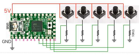
この回路図の5個しか使用していますが、Teensy2.0では16個まで使用できます。
まず、Arduinoのメニューからツール>Teensy2.0を指定、ツールメニューのUSB TyoeではKeyboard+Mouse+Joustickを選択して、書き込み。これでUSBジョイスティックとして認識されます。
XPlaneを起動、ジョイスティック&機器の軸タブでは赤枠のように、表示されています。
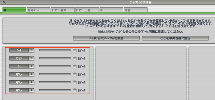
Teesyで書き込んだ後、この画面が出ればうまく行っています。
しかし、何も表示されないとか、3つだけ表示(他のジョイスティック)とかになります。
うまく表示されない場合は、再起動したり何度も、何度もやっていると上の状態になる可能性もあります。
ボタン:上級タブでは、作成したプッシュボタンを押すとチェックが入り、X-Planeのコマンドを登録することができます。
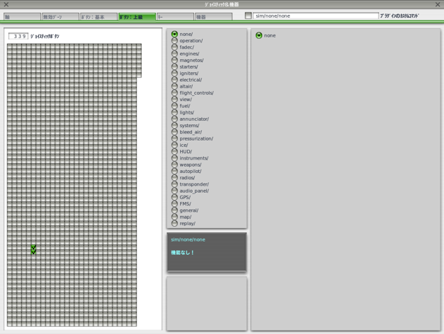
キーボードボタンを作成するより、こちらの方がまだ沢山の設定ができるので有用ですね。
まだ軸の使い方が分かっていません。可変抵抗を接続しているのですが、動作しません。
Teensy>USB_Joystick>Buttonsでも同じようにボタンを使うことができます。コード的にButtonsの方が分かりやすいのですが、コードが長くなるので、実際に使用する分には下のコード「Complete」のほうが実用的だと思います。
JoyStickComplete.ino
/* Complete USB Joystick Example
   Teensy becomes a USB joystick with 16 or 32 buttons and 6 axis input

   You must select Joystick from the "Tools > USB Type" menu

   Pushbuttons should be connected between the digital pins and ground.
   Potentiometers should be connected to analog inputs 0 to 5.

   This example code is in the public domain.
*/

// Configure the number of buttons.  Be careful not
// to use a pin for both a digital button and analog
// axis.  The pullup resistor will interfere with
// the analog voltage.
const int numButtons = 16;  // 16 for Teensy, 32 for Teensy++

void setup() {
  // you can print to the serial monitor while the joystick is active!
  Serial.begin(9600);
  // configure the joystick to manual send mode.  This gives precise
  // control over when the computer receives updates, but it does
  // require you to manually call Joystick.send_now().
  Joystick.useManualSend(true);
  for (int i=0; i<numButtons; i++) {
    pinMode(i, INPUT_PULLUP);
  }
  Serial.println("Begin Complete Joystick Test");
}

byte allButtons[numButtons];
byte prevButtons[numButtons];
int angle=0;

void loop() {
  // read 6 analog inputs and use them for the joystick axis
  Joystick.X(analogRead(0));
  Joystick.Y(analogRead(1));
  Joystick.Z(analogRead(2));
  Joystick.Zrotate(analogRead(3));
  Joystick.sliderLeft(analogRead(4));
  Joystick.sliderRight(analogRead(5));

  // read digital pins and use them for the buttons
  for (int i=0; i<numButtons; i++) {
    if (digitalRead(i)) {
      // when a pin reads high, the button is not pressed
      // the pullup resistor creates the "on" signal
      allButtons[i] = 0;
    } else {
      // when a pin reads low, the button is connecting to ground.
      allButtons[i] = 1;
    }
    Joystick.button(i + 1, allButtons[i]);
  }

  // make the hat switch automatically move in a circle
  angle = angle + 1;
  if (angle >= 360) angle = 0;
  Joystick.hat(angle);

  // Because setup configured the Joystick manual send,
  // the computer does not see any of the changes yet.
  // This send_now() transmits everything all at once.
  Joystick.send_now();

  // check to see if any button changed since last time
  boolean anyChange = false;
  for (int i=0; i<numButtons; i++) {
    if (allButtons[i] != prevButtons[i]) anyChange = true;
    prevButtons[i] = allButtons[i];
  }

  // if any button changed, print them to the serial monitor
  if (anyChange) {
    Serial.print("Buttons: ");
    for (int i=0; i<numButtons; i++) {
      Serial.print(allButtons[i], DEC);
    }
    Serial.println();
  }

  // a brief delay, so this runs "only" 200 times per second
  delay(5);
}
- 低価格コクピットの自作
- DataRefEditor
- プルアップとプルダウン
- Nav1の周波数の設定をロータリーエンコーダで行う
- スロットルコントロール
- イグニッションキーコントロール
- 針路バグコントロール
- 針路バグとエレベータトリムの切り替え
- 回転動作を粗いと微細で設定 & 3つのモードの切り替え
- ギアのアップダウンコントロール
- ロータリーエンコーダの色々な数値の設定
- トグルスイッチコントロール
- ロータリースイッチコントロール
- Teensy&キーボードボタン
- Teensy&ジョイスティックボタン
- プッシュスイッチでトグルを実現
- プッシュスイッチでLEDをONにしたままにする
- Teensy & I2C接続キャラクターLCDモジュール
- 7セグで数字を表示
- X-Plane LED ON/OFF
- マウスホイールの活用
- B 737-800
- B747-400
- B 777 Worldliner
- SiteMap
Contents